The Foundation of Machine Vision: A Complete Analysis of Camera Calibration Technology
Camera calibration is an irreplaceable foundational core technology in the field of machine vision. Its accuracy directly determines the measurement precision and reliability of the entire vision system. In today's era of comprehensive intelligent manufacturing upgrades—from chip pin inspection in 3C electronics to welding robot guidance in automotive manufacturing, from environmental perception in autonomous driving to minimally invasive surgical navigation in medical imaging—almost all intelligent applications that rely on vision cannot function without high-precision camera calibration.
This article from Dafan Optics systematically organizes the core principles, mathematical models, mainstream methods, and industrial practice workflows of camera calibration. Combining industry application cases and technology trends, it provides a concise and practical technical reference for practitioners.
I. Technical Essence: From Camera Imaging to Geometric Mapping
Modern cameras are essentially photoelectric conversion devices based on optical imaging principles, with a core composed of a lens system, shutter, photosensitive element, and image processor. Their imaging process can be simplified to a pinhole imaging model: when the object distance is much greater than the focal length, the lens group is equivalent to a pinhole. Objects in the three-dimensional world form an inverted real image on the imaging plane through the pinhole. For calculation convenience, the imaging plane is usually translated between the pinhole and the object to form an upright virtual imaging plane.
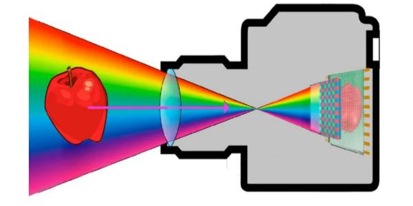
Camera calibration is the process of determining all unknown parameters in the mathematical model of camera imaging through experiments or algorithms. It is divided into two categories: intrinsic parameters and extrinsic parameters.
Its core value lies in three points:
Dimensional Quantification: Establishes the corresponding relationship between pixel coordinates and real-world physical dimensions, enabling direct measurement from images.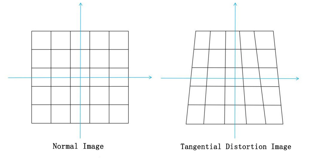
Distortion Correction: Eliminates image deformation caused by lens manufacturing and installation errors, restoring the true shape of objects.
Spatial Positioning: Realizes coordinate transformation from 2D images to 3D space, providing the foundation for robotic grasping and 3D reconstruction.
II. Core Mathematical Model and Parameter System
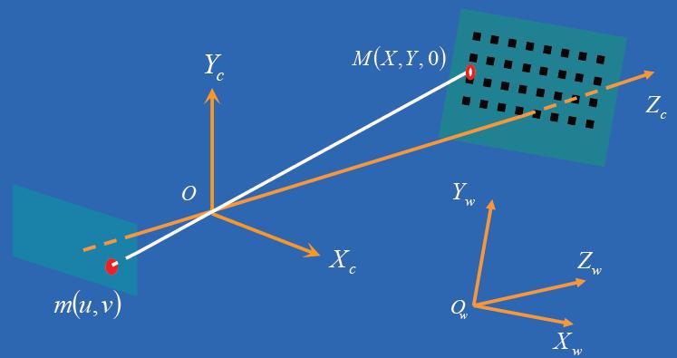
Camera imaging is essentially the sequential transformation of four coordinate systems: World Coordinate System (describing absolute object positions) → Camera Coordinate System (with optical center as origin) → Image Coordinate System (with principal point as origin, unit: mm) → Pixel Coordinate System (with image top-left corner as origin, unit: pixel).
Core Parameter System Includes:
Intrinsic Matrix K: Describes the camera's optical characteristics, including the focal lengths in x/y directions (fx/fy), principal point coordinates (u0/v0), and axis skew coefficient γ (approximated as 0 in modern cameras).
Extrinsic Matrix: Composed of a rotation matrix R and translation vector T, realizing the rigid transformation from the world coordinate system to the camera coordinate system.
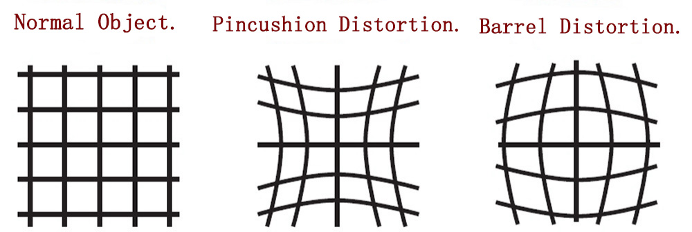
Distortion Coefficients: Include radial distortion (barrel and pincushion, caused by lens curvature) and tangential distortion (caused by the lens not being parallel to the imaging plane). Image deformation can be corrected using corresponding formulas.
III. Comparison of Mainstream Calibration Methods and Industrial Selection
Currently, the industry primarily utilizes three types of calibration methods, each with its own advantages, disadvantages, and applicable scenarios:
Method Category | Representative Technique | Accuracy | Operational Complexity | Core Applicable Scenarios |
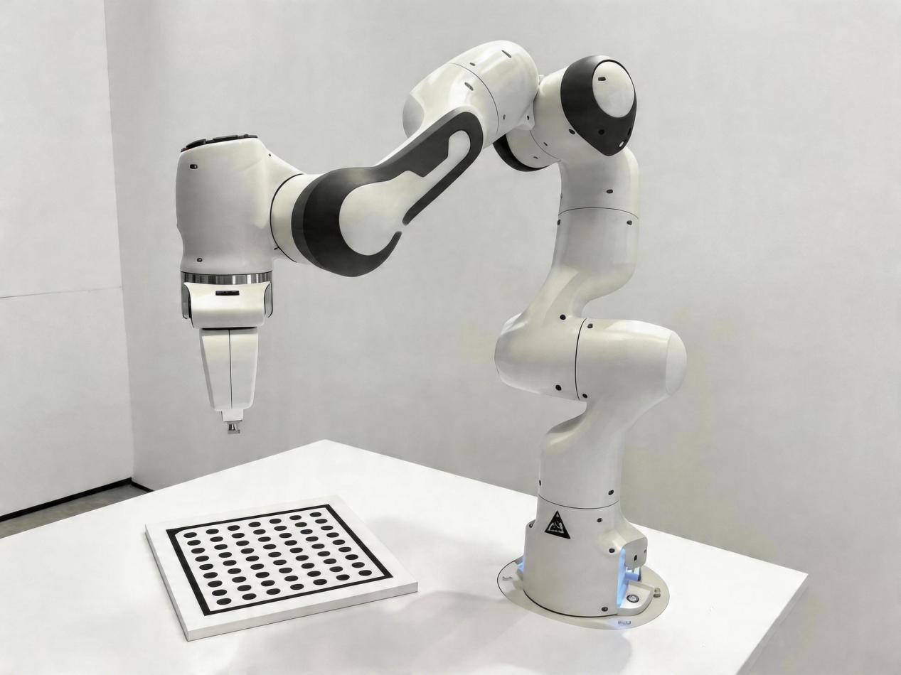
Target-Based | Zhang's Checkerboard Calibration | High (<0.5 pixel) | Low | Industrial inspection, general machine vision (industry standard) |
Target-Based | Circular Calibration Pattern | Extremely High | Medium | Medical imaging, precision measurement |
Active Vision | Motion-Controlled Calibration | High | High | High-precision laboratory measurement |
Self-Calibration | Scene Features / Deep Learning | Medium-High | Low | Outdoor SLAM, autonomous driving |
Industry Preferred Choice: Zhang's Checkerboard Calibration Method
This method, proposed by Professor Zhang Zhengyou in 1998, has become the industry standard due to its balance of accuracy and ease of use.
Core Workflow: Print a checkerboard calibration target of known dimensions → Capture 15-20 images from different angles → Detect corner points and perform sub-pixel optimization → Solve the homography matrix to obtain initial parameters → Perform nonlinear optimization via the Levenberg-Marquardt algorithm → Verify reprojection error and save parameters.
IV. Industrial-Grade Standard Calibration Workflow and Precision Control
1. Pre-Calibration Preparation
Prioritize selecting calibration targets made of ceramic or glass materials (high flatness, not easily deformed). Choose the grid size based on the field of view, ensuring the imaged area occupies 1/3 to 1/4 of the frame. Secure the camera bracket and adjust the light source to ensure uniform illumination without reflections. Install calibration tools such as OpenCV, Halcon, or Matlab.
2. Image Capture Specifications
Fix the camera's focal length and aperture (strictly prohibited from adjustment after calibration). Capture 15-25 images covering the four quadrants and center area of the frame, taking 2-3 images per area at tilt angles of 0°-30°. Avoid motion blur, overexposure, and underexposure.
3. Calibration and Accuracy Verification
Import images and automatically detect corner points, rejecting substandard images. Run the algorithm to calculate intrinsic/extrinsic parameters and distortion coefficients. Calculate the reprojection error; industrial-grade requirements demand it be less than 0.5 pixels. If the error is too large, check the calibration target flatness, image quality, or re-capture images.
4. Common Error Optimization
Use high-precision fabricated calibration targets to reduce manufacturing errors. Employ sub-pixel refinement to improve corner positioning accuracy. Control ambient temperature to prevent thermal lens deformation. Increase the number of calibration images to cover more viewing angles.
V. Core Industrial Applications and Implementation Cases
Industrial Inspection: Achieves workpiece dimension measurement, surface defect identification, and precise robotic grasping. An automotive parts enterprise enhanced engine cylinder bore diameter measurement accuracy from 0.1mm to 0.02mm using calibration, tripling inspection efficiency.
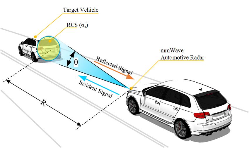
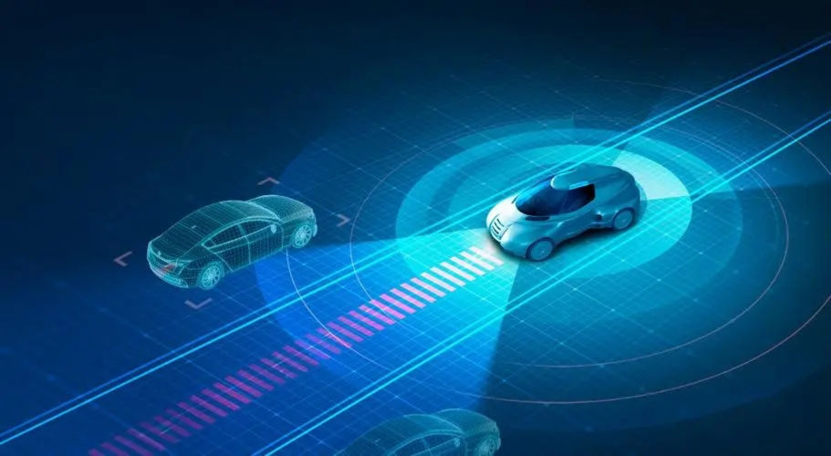
Autonomous Driving: Provides the foundation for monocular lane detection, binocular depth estimation, and multi-sensor fusion, unifying the coordinate systems of cameras, LiDAR, and millimeter-wave radar.
Medical Imaging: Corrects wide-angle distortion in endoscopes, aiding minimally invasive surgical navigation; precisely calculates lesion size and position, providing a basis for diagnosis.
3C Electronics: Inspects chip pin flatness and spacing, guiding robots to complete precise component placement and soldering.
VI. Technical Challenges and Future Trends
The future technology will evolve in five directions:
Online Real-Time Calibration: No downtime required; automatically compensates for parameter changes caused by environmental factors.
AI End-to-End Calibration: Reduces manual intervention and automatically handles complex distortions and environmental interference.
Unified Multi-Modal Calibration: Establishes a unified calibration framework for LiDAR, ToF, and RGB cameras.
High-Precision Calibration: Moves towards sub-micron level accuracy to meet semiconductor manufacturing demands.
Calibration Health Management: Real-time monitoring of calibration status for predictive maintenance.
Conclusion
As the foundation of machine vision, calibration precision directly impacts the reliability of the entire system. Traditional methods like Zhang's calibration are maturely applied in industrial scenarios, while self-calibration and deep learning technologies are pushing their popularization into complex environments.
In the future, as high-precision sensors and intelligent algorithms advance, calibration technology will continue to evolve towards automation, real-time operation, and multi-modal fusion, providing stronger support for fields such as intelligent manufacturing, autonomous driving, and medical diagnosis.
Latest News